Motivation
Ever since I bought some of Kitronik’s :move buggies I’ve been interested in making robots with the Micro:bit. They’re simple to program, have a decent set of features, and the kids enjoy using them. However they’re also a royal pain to assemble due to fiddly screw locations, quite expensive for what they are (we pay around $60AUD for what amounts to about $15-20AUD in components), and difficult to add on to due to cutting you off from all the additional pins the Micro:bit has to offer.
This year I looked into alternatives. There some 3D printed designs on Thingiverse which also use the same servo:lite board, but are much easier to assemble (design 1, design 2), but my main issue with 3D printing is how long it takes.
I found an interesting stick insect design which looked like it would lend itself to laser cutting instead and as a bonus didn’t use continuous rotation servos, and so my Year 9 class put together a few and had a go at writing some code to get them to move. Although they looked promising for simple linear movement, the added weight of using MDF instead of ABS/PLA meant they were not very successful, and traction was an issue, so we chalked it up to a learning experience, fiddled with LED code on the servo:lite boards, and practiced writing remote control code with the Micro:bit radios instead.
I liked the idea of using standard servos instead of continuous rotation (because they’re cheap!) so I sat down to design my own robot.
Design
Although I did technical drawing aeons ago at school, drafting is not really my strong suit (if I indeed have a strong suit). I drew up some rough plans, mostly while waiting for meetings to start.
-
 1 Linear actuator design
-
 2 Motion ideas for linear movement
-
 3 Ideas for elevation and steering
-
 4 Closing in on the final design
I started from my linear actuator designs, since there would need to be some linear movement - I initially imagined it as a pair of geared pontoons with a lifter underneath the robot, and played around with some ideas of having the lifter rotate so that the robot could steer. Although I still like this idea, keeping the cabling free and the interior robot layout nixed that idea and I went for a more traditional ‘wheel’ approach, each driven by a servo, and having a third servo to elevate the body so that the wheels could reset.
The final design went through about six iterations due to issues with weight distribution of the mobile phone power bank I wanted to use for a battery and also the fiddliness of aligning the actuator rod and installing guides so that it moved in a straight line and didn’t catch on the edges of the slot.
Keeping the actuator rod running smoothly up and down without catching on any other part of the chassis was the hardest part of the design, and the trickiest to assemble once it was cut out. I originally had three pieces surrounding the rod which each had to fit into holes in the top and bottom plates, and it was incredibly difficult to align while also keeping the servos and rod in place. I ended up scrapping that design and going for a simple two support design instead. Utilising a cross shaped support for the actuator rod instead of an L shape also made building supports a lot easier.
Assembly
Here’s a step-by-step process for assembly of the robot.
The main problem areas are:
- Getting the actuator rod height right as you assemble, since it needs to be taken apart to adjust it. My guide for this is set the gear servo to 60 degrees before insertion, then insert the rod so that it is about 3mm below the top plate, using the guides which surround the rod as a, well, guide.
- Holding the whole thing together while the top plate is attached can be a challenge, as can aligning the guide rods. The servos hold the top plate roughly in place, so you can poke a finger or some small object in to push the tops of the guides into their holes to snap into place.
- Align the wheel servos to their forward positions before attaching the wheels. I use 110 degrees for the right, and 40 degrees for the left servos (since my cheap servos have some funny working ranges).
-
 01 Cutting six robots
-
 02 One robot ready to assemble
-
 03 Actuator rod and attachment to base
-
 04 Rod attached to lifter base
-
 05 Gear fitted snugly to the servo
-
 06 Servos held in place by slots and cabling
-
 07 Bottom view of cabling
-
 08 Rod supports in place
-
 09 Rod inserted to just below top plate height
-
 10 Top plate attached
-
 11 Side supports hold frame together
-
 12 Top view of partial assembly
-
 13 Attach one front support
-
 14 Attach microbit platform
-
 15 Slide support into platform
-
 16 Push wheels on after servo alignment
-
 17 Work complete
Code
I have some sample code for movement and a more fully functional remote control scheme sitting into Github repo for this project.
The movement itself is quite simple though, and just involves a series of these steps:
- Extend elevator rod
- Reposition wheels
- Retract elevator rod
- Move wheels to drag robot
# servo pins
bottom = pin8
left = pin12
right = pin16
# angles for motion
fwd = [110, 40] # right, left
bck = [65, 85] # right, left
# angles for retraction and extension
retract = 65
extend = 90

# 'walk' cycle consisting of:
# instruct servos to move
# sleep to give enough time to arrive at angle
bottom.write_analog(extend)
sleep(150)
right.write_analog(fwd[0])
left.write_analog(fwd[1])
sleep(200)
bottom.write_analog(retract)
sleep(150)
right.write_analog(bck[0])
left.write_analog(bck[1])
sleep(200)
Outcome
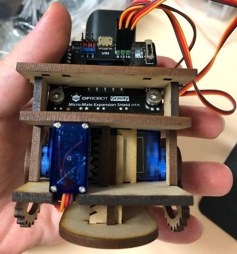
Front view through to actuator
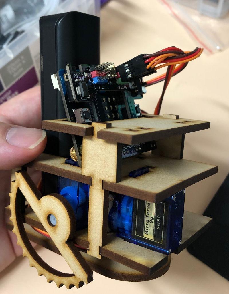
Side view
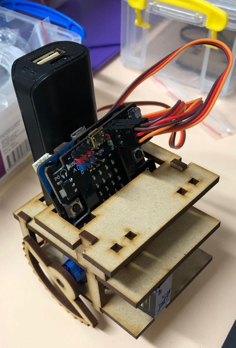
Top view
I ended up putting some mounting points for additional sensors and outputs like LEDs at the front. The whole thing snaps together and generally doesn’t require glue to hold anything together (although occasionally due to slight warping of the MDF sheets some of the pegs end up looser than others).