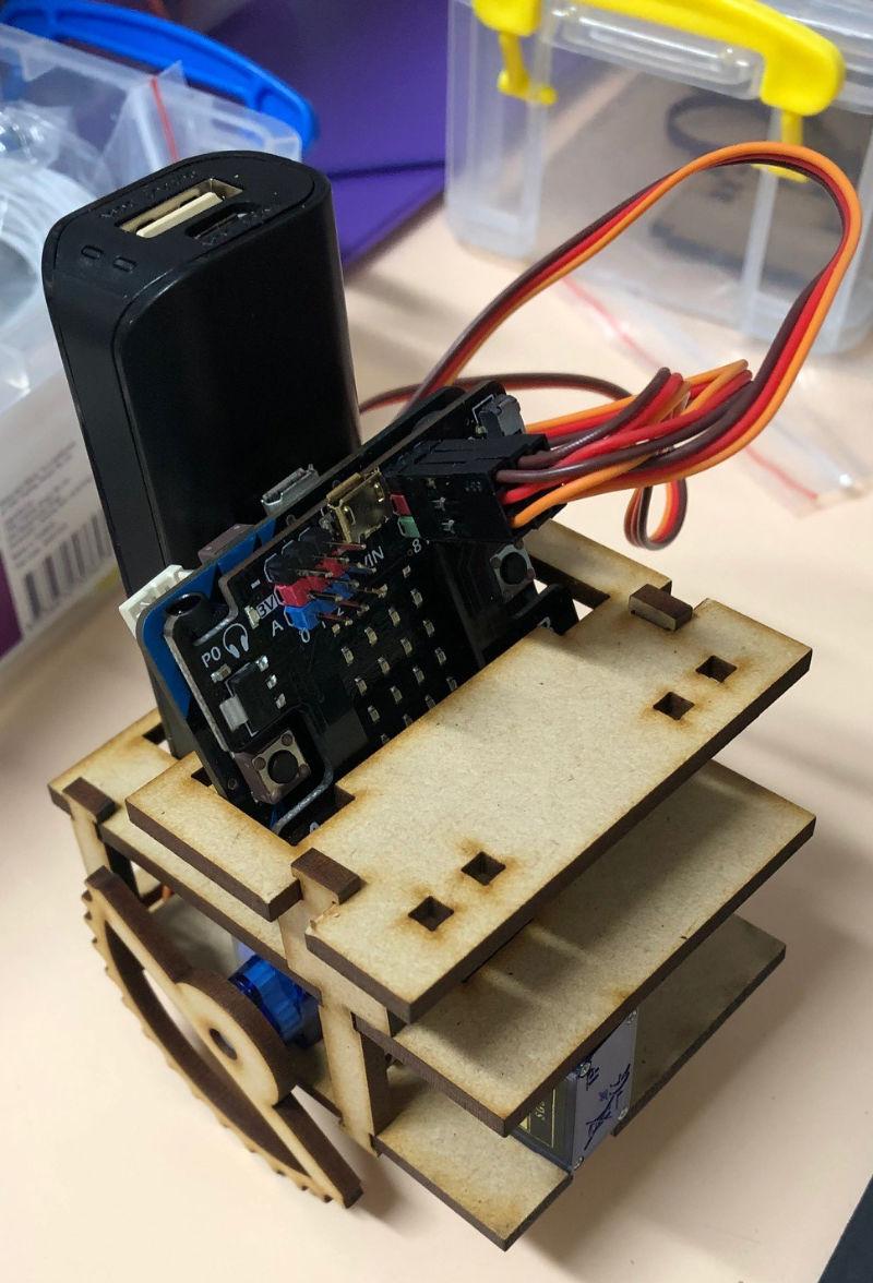
This post is intended to be a bit of a primer for teachers interested in getting into more varied use of the BBC Micro:bit beyond the inbuilt basics. My intention is to put together two posts: this one on the hardware and the ecosystem, and another on approaches in the classroom (which will mostly be a list of mistakes I’ve made and thoughts on doing things beter).
This is by no means an exhaustive list of things you can do or components available. I’ve generally experimented with cheap and cheerful parts that I can source myself for a few dollars to see if it’s worth implementing in the classroom. I still have a long list of things I want to try! The components listed here I’ve generally had good success with.
Lastly, I don’t have a background in electronics, so apologies for anything I’ve gotten wrong! If you have Feelings about any errors and want to let me know, ping me at rob at this domain and I’ll fix things up.
Digital vs Analog
One of the things that pleasantly surprised me about figuring out basic sensors and outputs is the difference between digital and analog signals. Once you understand the difference between the two, the Micro:bit makes both types quite pleasant to work with (with the caveat of knowing what devices are 3.3V).
Both Digital and Analog signals simply refer to the voltage being input or output on a pin.
Digital devices are either on or off, so voltage is either low or high, which is mapped to either being a 0 or 1 when reported to whatever programming environment you are using (such as MakeCode or MicroPython). Devices such as infra-red motion sensors are general integrated circuits which generate a digital signal, as when they detect motion they set the voltage being deliverd to the data pin to full, and after a pre-set time the voltage sent to the pin will be set to off.

Pupper only cares if the water is on or not.
Analog devices output or input a range between 0 and full voltage. Rather than dealing with real voltages, this is mapped to a range of integers. For the Micro:bit this is from 0-1023 (a 10 bit binary number) although you can customise this width for other platforms (such as the ESP32). Examples of analog input devices are light dependent resistors.

An analog signal can be part of the whole potential signal.
Analog output with Micro:bits is done via Pulse Width Modulation (PWM) rather than by changing the voltage directly. What this means is that the Micro:bit splits its output into small slices of time, and turns the pin to high voltage for enough of each slice to average out the power to the desired amount (called a duty cycle). This works fine with some components, but not others which expect continuous power.

This sprinkler puts out bursts of water as it cycles.
Components
All of these components can be sourced cheaply from China; I tend to buy most of my gear through AliExpress. You can buy the same things (often attached to fancier addon boards) from the hobby/education sites, but usually at a very significant markup, which is not really workable when I often want to build custom projects that are heavy on the hot glue and solder.
Most of these are pretty simple, but a few like the infrared sensors aren’t just the basic sensor.
Common Ground
One of the things that took me a while to figure out (because in general I have been figuring things out as I go) is when using different power sources for higher power components such as the LED strips and servos, the ground pins of the Micro:bit and the extra power source need to be connected.
Light Dependent Resistors (LDR)
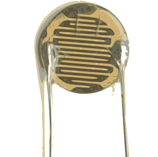
LDRs are brilliant simple little sensors. You pass power through them, and they change the their resistance depending on how much light is being shone on them. When reading analog data from the LDR, the intensity maps to the number recorded. Although they’re pretty consistent, I’ve had some LDRs from the same batch report slightly different numbers, so it’s worthwhile doing some calibration before use.
Wiring is pretty straightforward:
- One leg is connected to voltage
- The other leg is connected to both a resistor (10kOhm) going to ground, and to a data pin on the Micro:bit.
Some uses:
- Detect whether a door has been opened.
- Turn on/off lights based on ambient light level (digital behaviour) or change light brightness or colour (analog behaviour).
- Sensors for ’light guns’ (see my haunted house project).
- Particlulate sensor for liquids (shine a known intensity light through sample, detect amount that gets through).
Light Emitting Diodes (LED)
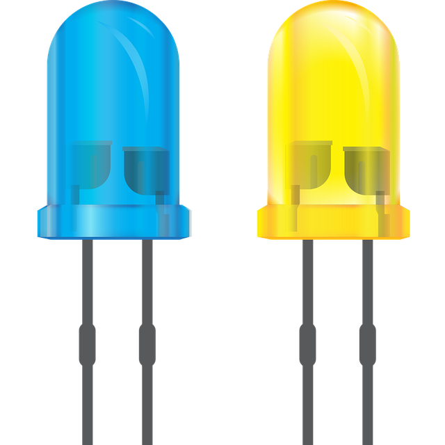
LEDs come in a few different flavours. Typically the vanilla LEDs will come in several different colours (while, blue, yellow, orange, red and green) and a couple of different sizes (5mm and 3mm diameter). They work well in both a digital (on/off) and analog (brightness, using PWM) context. Although there are slight differences in power requirements, using 100 Ohm resistors for all of them keeps things simple and works fine.
Source: Flickr - Original author Oomlout CC-BY-SA
On the fancier side of things are RGB LEDs, which can be set to any colour by mixing red, green and blue amounts. This comes with some extra overhead in terms of pins (which could still be used either as analog or digital, although more usefully as analog to control the intensity of each colour channel). I generally find these a bit too fiddly and prefer to have pins free to use for other purposes.
Where LEDs get a bit more interesting are the collections bound up with individually controllers, so that each LED in a strip (or panel) can be individually addressed. There are a couple of common controllers that seem to be equivalent (and from what I’ve read, sometimes when you order one you get the other): WS2812 and SK6812. These often come under Adafruit’s branding of Neopixel, but this is what they are under the hood, and they work the same way.
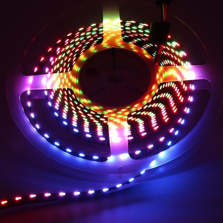
The beauty of these LED controllers is that you can chain them together and change their colour individually (as well as turning them on or off) with only one data pin and a power supply. The down side is that they are not rated for 3.3V and so you need to mix in an external power supply (I usually use 3xAA batteries for most of my projects that need more juice). You can buy these individually or in strips, but can always separate the strips in shorter ones and use them separately.
I came across this hack for running these lights off 3.3V and will have to try it out with the Micro:bit.
When running a single LED for learning about the components, these LEDs run Just Fine from the standard 3.3V output of the Micro:bit. I have soldered a bunch of single LEDs to 3 pin female headers and use them when teaching about colour theory and letting students practice the basics of setting them up and controlling them.
Servos
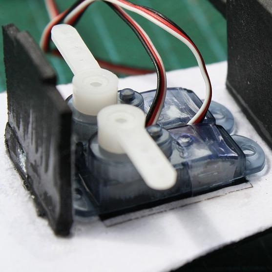
I have a love/hate relationship with servos. On one hand, they fulfil a huge role in so many interesting hobbyist electronics projects, and on the other hand I have had so many finnicky problems with them in terms of reliability when not controlled by addons like the Servo:Lite board that presumably handle power regulation.
Servos come in two varieties: continuous and standard. Continuous servos simply keep rotating in whatever direction and at whatever speed you tell them to (and thus are useful for [rather noisy] motors to drive wheels). Standard servos rotate to a specified angle and then stop, and are usually constrained to 180 degrees, although the cheaper varieties I use typically have a reliable range somewhere between 35 and 120 degrees.
Both are very simple to program by sending an analog signal corresponding to the angle (or speed for continuous rotation) to move to. A value of 0 is typically off, but I believe this works slightly differently with MicroPython compared to MakeCode.
Some uses (mostly obvious):
- Driving wheels (continuous)
- Gondola driver pulley (continuous)
- Eye/mouth movement (standard) see Stu Lowe’s excellent animatronics stuff driven by 3D printed linear actuators run by continuous servos (and a bonus ping pong ball cannon)
- Steering (standard) see my laser cut steering assembly
- Opening doors/windows (standard or continuous, depending if you wanted to rotate or drive a linear actuator to raise/lower something)
Potentiometer
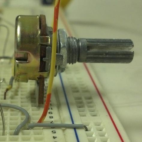
Potentiometers are a variable resistor where as you turn the knob there is more/less resistance applied. They are very simple to wire up, with voltage and ground hooked up to either side, and the central pin connected to a data pin.
Potentiometers are quite useful for a number of different applications:
- Control the angle (or speed for continuous rotation) of a servo.
- Control the delay in between actions (e.g. blinking of an LED).
- Change frequency or tempo of music.
- Change red/green/blue component of LEDs.
Be aware that there are different types of tapers for potentiometers: linear and logarithmic. Linear taper potentiometers change their resistance at a constant rate as they are turned, whilst logarithmic taper potentiometers do not. Linear taper potentiometers have a B before the resistance rating. e.g. B10K indicates a linear taper 10 kOhm potentiometer.
Speakers/Headphones
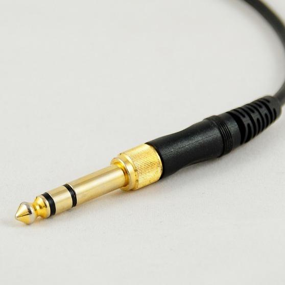
One of the things I found surprising was MicroPython’s speech library and how terrible-yet-quite-usable the quality was, considering how constrained the Micro:bit is. The tone generation in the music library is also quite usable in a few different ways (note, register, duration or by frequency).
Sound output on the other hand, is not very pleasant. You can hook up headphones and basic speakers very easily (data pin and ground), but volume control is not something you get as part of the package. Headphones tend to be uncomfortably loud, while speakers are prohibitably soft (for a class of 20 or so students). You can amplify using addons like Proto-Pic’s amp:bit board, but that also hides the rest of the Micro:bit’s pins from use.
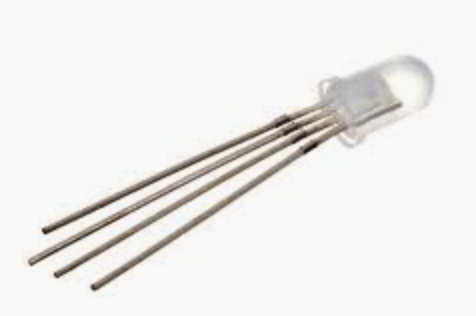
Mini InfraRed Sensors (Mini PIR - AS312/AM312)
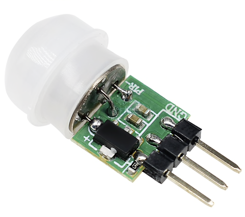
These PIR sensors are quite sensitive, in my testing triggering from about 3m away from the sensor for a human sized body. Unlike larger sensors there doesn’t seem to be a way to change the amount of time the pin goes high for when it senses a heat source, with these triggering for about 2 seconds in my experience.
These devices are used in a digital context, where 0 would indicate no motion sensed, and 1 that the sensor had been triggered. The 1 continues to be read for however long the triggered period is, so your code needs to cope with that (possibly waiting until the pin goes low to 0 again, depending on what else is happening in your execution loop).
Line Follower IR Sensors (TCRT5000 based)
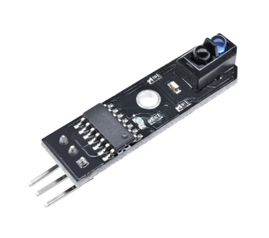
The line following sensor works in a similar way to the other IR sensor, but designed for reflected IR radiation at very short range. While it can be used for the intended purpose, I found this was also useful for detecting when items had been put into a container as well. One of my students created a donation box that thanked the donator when it detected something had passed the line sensor.
I’m sure there are other unintended short range sensing uses for it as well (which is good because I accidentally ordered 20 of them instead of 2 because they were so cheap and I didn’t read the item description carefully enough).
Temperature Sensors
Although the Micro:bit has a temperature sensor built in, it doesn’t measure ambient temperature. Rather, it is the temperature of the device, and because it is integrated into the board, makes it less useful for measuring spot temperatures of any location that isn’t at least the size of the Micro:bit itself.
When I started looking at using Micro:bits, I already had some Arduino components sitting around, so I thought I’d have a go at getting them working. The DHT11 (temperature and humidity sensor) is pretty common and I had a couple of them, but apparently the Micro:bit can’t drive it (and library which is present in the main MicroPython distribution isn’t present in the Micro:bit flavour).
I have had a play with 10kOhm thermistors, which are basically the same as an LDR but for temperature (and wired the same way). They’re fine for measuring changes in temperature, but you would need to calibrate the analog readings against known temperatures to turn it into a traditional temperature measurement.
I finally ordered some TMP36 sensors, which work off 3.3V and do give you an accurate temperature reading (after dividing by 10) without the need for your own calibration process. As a bonus, they’re quite cheap (I paid around $3 for 5).
Custom Addons
As well as looking at individual components, I’ve used a few different custom expansion boards, as well as some basic breakout boards to access the rest of the Micro:bit pins.
Although these will generally improve the usability for the components which they are designed for (the servo boards in particular), they often tie up more pins on the board than they need to, restricting integration with other components.
Because of the very easy networking available with the Micro:bit, it is possible to work around these limitations by using multiple devices, but it adds to the complexity to program for syncing and message passing in addition to sensing and control.
These boards have a strip of 5 NeoPixel LEDs, 2 sets of pins for servos, and a 3xAAA battery backpack. Apart from a slight design issue with clearance for the USB cable to the Micro:bit being very tight (it works with the cables that come with the Micro:bit but many other USB cables don’t fit), they work brilliantly. The downside is the board screws onto all the terminals of the Micro:bit, so you can’t attach any other devices.
They have been very reliable for servo control, and the lights are a nice bonus.
If all you want to do is control servos, and lots of them, then this is for you. You can get a MicroPython moduly for controlling it from this GitHub repo. It uses I2C, so my understanding of how it works is nonexistant, but it works fine (I used it for the servo control of my haunted house project).
The Amp:bit is a nice way of hooking up speakers and headphones. It has contacts for soldering on pins or direct connections to a speaker, and as a 3.5mm jack for plugging in headphones, as well as a much needed volume control.
Again, this board cuts you off from using the rest of the pins on the Micro:bit as it uses a slot-in system like most expansion boards, and provides no other contacts. A better solution seems to be the Monk Makes Speaker, which doesn’t slot in the Micro:bit, allowing for more flexible projects.
I have a couple of these but just haven’t really used them much. Without a gearbox the small motors you generally get just don’t have the torque to drive much. I have however looked at some alternative uses for motors, like 3D printing water pump and air pump housings which look promising.
Originally I thought these would only do full power to motors, but apparently they do support PWM for slowing the motors down, which would make them more useful.
ZIP Halo RGB LED ring
These are basically a 24 LED WS2812 strip arranged in a ring around the Micro:bit. The board screws onto the terminals of the Micro:bit, but does break out a general purpose pin for other uses, as well as an extension pin for attaching more LEDs onto the ’end’ of the 24 provided. One of my student projects was one of these rings with a ring of 60 extended on the outside, to make a clock.
These addon boards screw onto the Micro:bit’s 0 and GND terminals, and use spring-loaded feet to break out 6 pins (0, 1, 2 and 8, 12 and 16). They have an additional MicroUSB port which can be used for 5V power delivery to pins 8, 12 and 6 (which can be switched between 3.3V and 5V) and also feeds power back to the Micro:bit (although it can’t be used for programming, which leads to lots of “why isn’t my Micro:bit being deteced - oh I have it plugged into the wrong port”).
They are quite cheap (around $10AUD) and I have found them to be quite reliable for hooking up servos, LED strips, and other higher power uses. Unlike the Servo:lite board, having 6 pins broken out means there is a lot of flexibility available.
Issues
A lot of electronics kit, particularly designed for Arduino, runs off 5V, rather than 3.3V. Whilst you can externally power some of these, it’s a bit less straightforward for others. Also, often the power requirements aren’t always obvious, for example some common ultrasonic range finders come in 5V and 3.3V varieties (HC-SR04 vs HC-SR04P).
One of my early problems working with Micro:bits and breakout boards is figuring out which pins are capable of what. For example, unless the display has been disabled, some pins are dedicated to driving that (and you’ll get an error about pins being in Display Mode, without much direction in what to do next - display.off() solves that problem). Some pins don’t do analog operations, two pins are reserved to trigger button A and B events, etc. A diagram and a decent explanation that outlines some of this is on the pins page of the Micro:bit site.
The biggest issue, which is not unique to the Micro:bit is the usual problem of figuring out whether something not working is the fault of bad code, faulty wiring, or faulty understanding of how the circuit is supposed to work.
Yet to dig into
I still have only a really hazy understanding of I2C and SPI. I know what they do, but the how is pretty vague. I still need to get my head around this.
The Micro:bits are great to work with in the classroom, but you pretty quickly hit a ceiling of what they can do with complex systems since there is only so much memory to go around. For example my Haunted House project’s servo code ran into the wall on numerous occasions when I was developing it (and the error messages you get for that are not helpful).
I’ve bought myself a couple of ESP32 boards to look at how practical they are to use (much cheaper than the Micro:bits, more resources, but not as much built in). The MicroPython environment is quite similar, you can get 802.11 and Bluetooth built in, threading and more. The downside is they don’t act as a USB storage device like the Micro:bit does, so flashing programs and firmware involves fiddling with COM ports, potentially install drivers, etc. There is an IDE which helps with this from DFRobot (https://github.com/DFRobot/uPyCraft) but I haven’t used it much yet.